
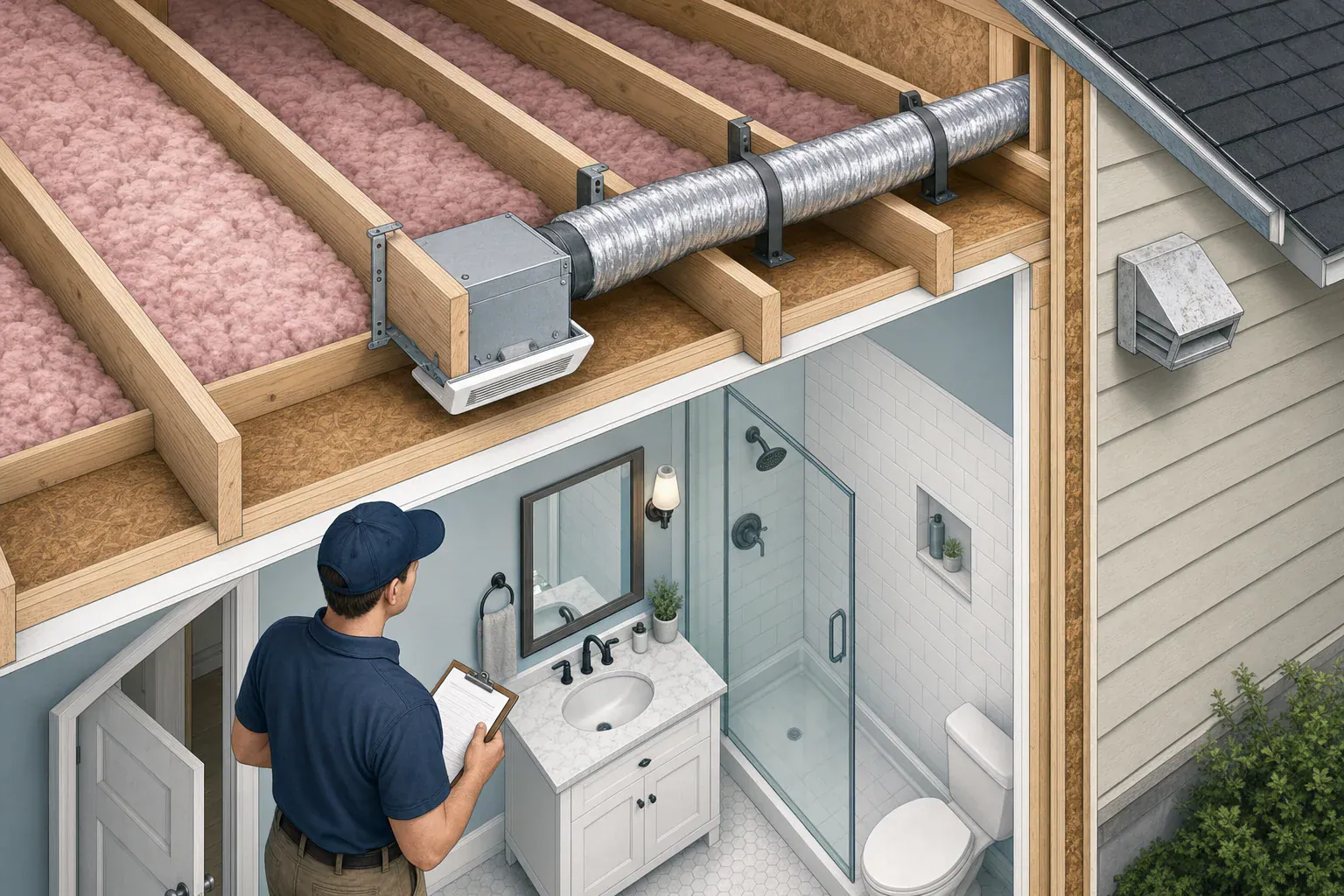
How to install a bathroom ventilation fan: plan before cutting
A first-time bathroom fan is more than a ceiling opening. The project may require a new housing, duct, outdoor termination, control, power connection, and inspections. Plan those parts as one system before buying a housing or cutting drywall.
Confirm these five points first:
- Pickup location: The proposed grille location can serve the bathroom and complies with the selected fan’s installation instructions.
- Framing: The housing can be attached as the manufacturer directs without an unapproved change to joists, studs, or trusses.
- Duct route: The specified duct can reach an outdoor termination without being crushed, excessively bent, or inaccessible for sealing.
- Termination: A compatible wall or roof cap can be weathered correctly and located to meet applicable local requirements.
- Power and controls: A qualified person or local authority has confirmed the electrical plan, permits, and inspections that apply.
If any one of these is unresolved, choose a different fan location or route before work begins.
Size airflow before choosing the fan housing
The Home Ventilating Institute (HVI) recommends 1 cubic foot per minute (CFM) per square foot for bathrooms under 100 square feet, with a 50-CFM minimum. HVI uses a fixture-based approach for larger bathrooms. This is selection guidance, not a replacement for the code adopted where the home is located.
The 2024 International Residential Code model text lists 50 CFM for intermittent bathroom exhaust and 20 CFM for continuous exhaust. The IRC is a model code: the locally adopted edition, amendments, and project conditions govern.
Hypothetical sizing example
Assumptions: A bathroom is 6 feet by 8 feet, the fan will run intermittently, and no different local requirement applies.
- Floor area: 6 × 8 = 48 square feet
- HVI area result: 48 CFM
- HVI minimum: 50 CFM
- Planning target: at least 50 CFM, then confirm that the selected fan and its allowed duct configuration can deliver suitable airflow when installed
A fan’s rated airflow is not proof of installed airflow. Duct length, bends, duct size, joint quality, and the exterior cap can all reduce the air moved by the completed system.
Choose ceiling or wall placement from the route
Start with a feasible path outdoors rather than assuming that a ceiling location is always best. The exact fan must be approved by its manufacturer for the planned orientation and mounting method.
| Option | May favor this option | Verify before selecting it |
|---|---|---|
| Ceiling mount | An accessible joist bay provides a practical route to a wall or roof cap. | Ceiling approval, housing depth, joist attachment, duct direction, insulation instructions, and access to seal duct joints. |
| Wall mount | An exterior wall creates a shorter route, especially where there is no accessible attic. | Explicit wall-mount approval, stud spacing, wall depth, exterior obstacles, weather detailing, and applicable termination clearances. |
A fan located in or directly over a tub or shower must be specifically listed by its manufacturer for that location and installed according to its electrical-protection instructions and local rules. Do not treat a general ceiling fan as suitable for a wet location. For example, a manufacturer’s instructions can permit wall mounting or specify protection for wet-area use, but those instructions apply only to that exact model—not to every fan.
Plan differently with and without attic access
| Access condition | Planning advantage | Likely complication |
|---|---|---|
| Open attic above | Framing, utilities, duct connections, air sealing, and insulation can usually be inspected directly. | Protect the finished ceiling and manage loose insulation. The duct still needs a supported, sealed route outdoors. |
| No attic access | A room-side-installable housing or a direct exterior-wall route may reduce disruption. | Exploratory inspection, access openings, and finish repair may be necessary to identify framing and complete the route. |
With finished space above, determine joist direction and investigate likely plumbing and wiring paths before making an opening. A stud finder or small inspection opening may help locate conditions at one point, but it cannot prove an entire concealed route is clear. Stop when an opening reveals an unidentified cable, pipe, framing member, or obstruction.
Plan the duct and outdoor termination together
The DOE Building America Solution Center recommends terminating bathroom exhaust outdoors and using smooth, correctly sized duct with few bends, sealed joints, and insulation where needed to reduce condensation. Follow the selected fan’s manual for duct diameter, approved materials, fittings, connections, and routing limits.
Compare routes on paper first
Sketch at least two possible routes from the fan to outdoors. Compare total run length, bends, ability to seal and support the duct, insulation needs, and whether a weather-resistant exterior cap can be installed properly. Do not reduce the duct diameter or improvise a transition unless the manufacturer explicitly permits it.
Avoid crushed flexible duct, sharp bends, low spots, and unsupported sections that can restrict airflow or collect moisture. Where duct crosses unconditioned space, use the insulation and condensation-control details required by the fan instructions and local rules. Do not assume a universal duct slope or drainage direction; those details depend on the product and installation.
Discharge outdoors, not into building cavities
The 2024 IRC model text requires bathroom exhaust to discharge outdoors and prohibits discharge into attics, crawl spaces, and other enclosed areas. Plan a compatible wall or roof cap and verify locally applicable clearances and weatherproofing details before cutting the exterior opening. A wall cap may create the shorter route; a roof cap may be more practical when it offers the cleanest route. Neither is automatically better for every home.
Do not assume a soffit termination is acceptable. Nearby openings, roof geometry, the fan instructions, and local requirements can affect the outcome. Roof penetrations and difficult exterior-wall details may be work for a qualified roofing or exterior-envelope contractor.
Include backdraft control in the route review
The fan housing or exterior cap may include a damper intended to limit reverse airflow when the fan is off. Confirm the specified damper is included, oriented correctly, accessible where practical, and free to open during operation and close after shutdown. Duct misalignment, sealant, paint, fasteners, or a restrictive cap can prevent free movement.
If the home has fuel-burning equipment, unusually large exhaust equipment, or several exhaust devices, seek a qualified assessment if there is uncertainty about pressure effects. The EPA’s remodeling indoor-air-quality guidance advises considering how exhaust equipment can affect combustion appliances.
Structural, electrical, and permit stop points
Framing
Match the housing to the available framing and the manufacturer’s attachment method. Do not cut, notch, or drill a joist or truss simply to make the fan or duct fit. Move the location, revise the route, or obtain project-specific direction from an authorized building professional.
Electrical work
A nearby light circuit is not automatically suitable for a new fan. The fan load, control arrangement, cable route, location-specific instructions, and required protection must be evaluated for the particular home and jurisdiction. Do not energize incomplete electrical work for a trial run.
Electrical permissions vary locally. For example, Portland’s residential permit guidance addresses permits and limits for new hard-wired work, while New York City’s electrical project guidance requires covered modifications to be performed through a Licensed Master Electrician. These are examples of local variation, not nationwide rules. The Electrical Safety Foundation International recommends qualified electricians who follow applicable state requirements and obtain required permits.
Permits and inspections
Ask the local building department whether mechanical, electrical, building, or exterior permits and inspections apply before work starts. Also check building-owner, landlord, or association requirements when relevant. A permit answer can change with the location, building type, and scope of work.
Commission the completed fan system
Commissioning checks the system as installed rather than relying on the fan’s label. DOE guidance notes that ducting and terminations can reduce delivered airflow and describes measurement with airflow-testing equipment.
- Inspect the housing: Confirm secure mounting, a properly fitted grille, and sealing that does not block required openings or service access.
- Inspect the accessible duct: Look for disconnected joints, compression, damage, sharp bends, unsupported runs, and missing or damaged insulation where it is needed.
- Observe the damper: Run the fan and confirm accessible dampers open. After shutdown, check that they close without binding.
- Check the outdoor cap: Confirm air exits outdoors and that the cap is not blocked.
- Measure airflow: Use an appropriate flow hood or other accepted method, or hire a ventilation professional. A tissue can indicate that air is moving, but it cannot quantify CFM.
- Compare the result: Compare measured airflow with the project target and locally applicable requirements. If airflow is low, inspect the duct route and cap before assuming the fan motor is defective.
- Verify controls: Confirm the switch, timer, humidity control, or other selected control operates as intended and is understandable to occupants.
Preflight and final verification checklist
- Room dimensions and airflow target documented
- Selected fan approved for the planned ceiling or wall orientation
- Joist or stud location confirmed
- Housing depth and attachment method checked
- Concealed plumbing, wiring, and obstructions investigated
- No unapproved framing alteration required
- Duct diameter and materials match the fan manual
- Route reaches outdoors with few practical bends
- Duct sealing, support, and insulation details planned
- Exterior cap location, weatherproofing, and applicable clearances verified
- Suitable power, circuit protection, and controls assessed by an authorized person
- Local permit and inspection requirements checked
- Backdraft damper opens and closes freely
- Completed housing and duct inspected for leakage or restriction
- Delivered airflow measured or professionally verified
Frequently asked questions
Can a bathroom fan vent into an attic or crawl space?
No. Plan for the duct to terminate outdoors through a compatible, properly weathered wall or roof cap. The 2024 IRC model text prohibits bathroom exhaust discharge into attics, crawl spaces, and other enclosed building spaces; confirm the requirements adopted locally.
How much airflow does a small bathroom fan need?
For bathrooms under 100 square feet, HVI recommends 1 CFM per square foot with a 50-CFM minimum. A 48-square-foot room therefore has a 48-CFM area result but a 50-CFM planning minimum. Check locally adopted code and account for the selected fan’s permitted duct configuration.
Can a tissue test verify bathroom-fan airflow?
No. A tissue test can show that some air is moving, but it does not measure delivered CFM. Confirm discharge at the outdoor cap, inspect the duct and damper, and use an appropriate flow hood or other accepted measurement method when airflow must be verified.
Related guides: Exhaust Fan Best Practices: Bathrooms and Kitchens That Actually Clear Air • How to Replace a Bathroom Ventilation Fan Safely • How to Clean a Bathroom Ventilation Fan Safely • Bathroom Fan Timer Settings to Prevent Mold After Showers
- Clear sizing logic (room size → CADR/ACH)
- HEPA vs carbon explained for real use-cases
- Humidity + ventilation basics to reduce mold risk