
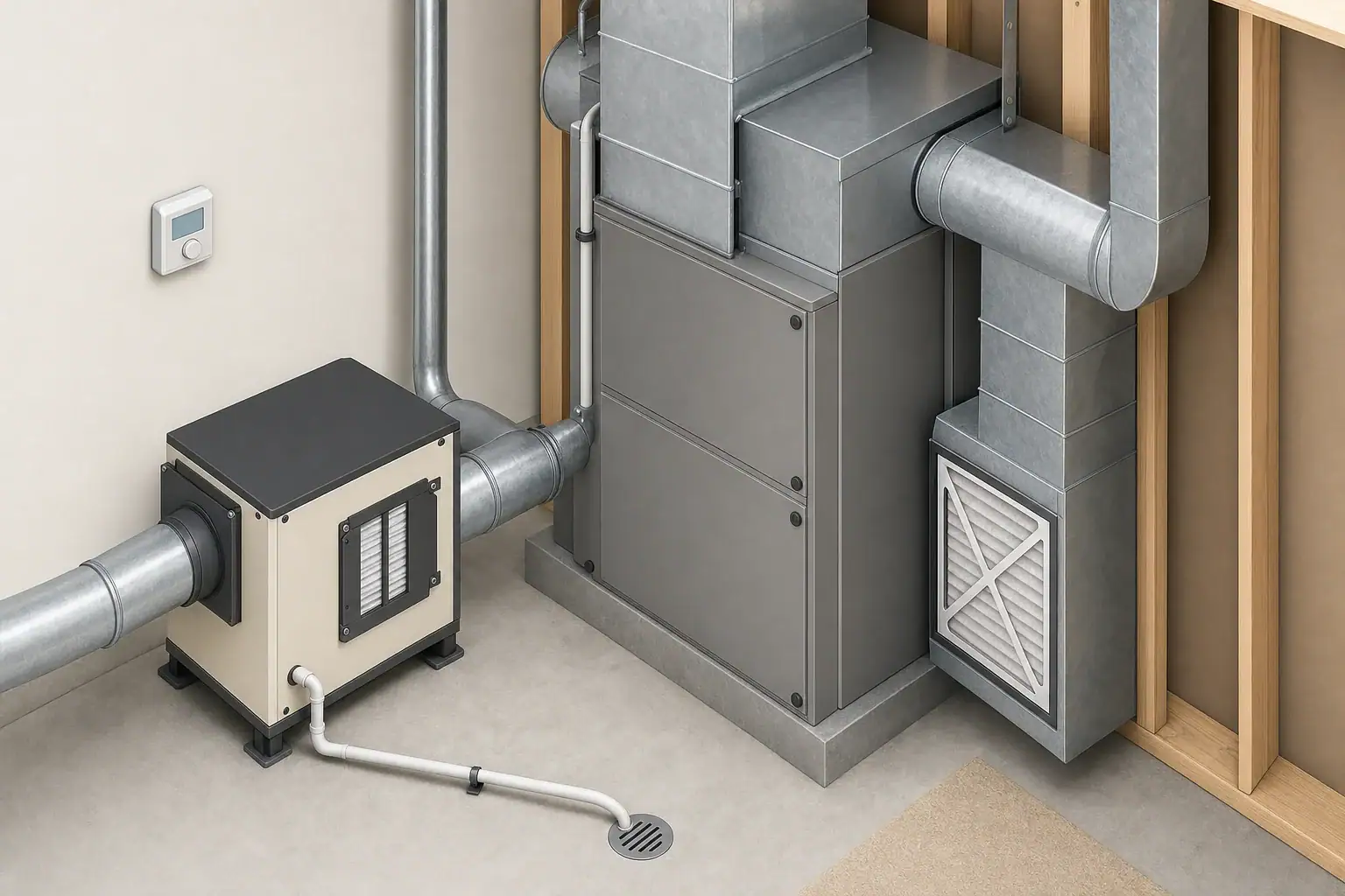
Plan before you install a whole-house dehumidifier
A whole-house dehumidifier retrofit is not a universal cut-and-connect project. The correct duct arrangement, drain configuration, wiring, controls, clearances, and operating sequence depend on the selected unit, the existing HVAC system, and local requirements.
Use this planning sequence before cutting ducts or mounting equipment:
- Confirm that the moisture problem is not primarily a plumbing leak, groundwater entry, roof leak, or another bulk-water source.
- Choose a location that meets the unit manual’s temperature, orientation, mounting, clearance, and access requirements.
- Select a duct layout specifically permitted by the manufacturer.
- Identify the manufacturer pressure limit and how airflow or external static pressure will be checked.
- Plan condensate disposal, overflow response, power, and control wiring.
- Check permit and inspection requirements with the authority having jurisdiction.
- Commission and document the completed system rather than relying only on whether it starts.
Choose a location with service and drainage access
The equipment location must support the unit in its required orientation and leave enough room to remove the filter, open service panels, connect ducts, and reach electrical and drain connections. Check the exact installation manual for allowable ambient conditions and model-specific clearances.
Plan the service path as well as the installed position. A unit may fit in a mechanical room but still be impractical if its filter or panels cannot be removed. For example, the AprilAire E130 installation and owner’s manual calls for 20 inches of filter-removal clearance for that model. Do not transfer that dimension to another unit.
Also consider vibration, noise in occupied rooms, exposure to water, drain access, and the route for future equipment replacement. Where leakage could damage a finished area, follow the unit manual and local requirements for a pan, float switch, pump-overflow shutdown, or other protection.
Compare whole-house dehumidifier duct layouts
The Pacific Northwest National Laboratory’s whole-house dehumidification guide describes independent duct systems and arrangements integrated with central HVAC ducts. The selected unit’s manual controls: permitted connection points, dampers, separation, blower operation, and lockouts vary by product.
| Layout | Main advantage | Critical planning issue |
|---|---|---|
| Dedicated return to dedicated supply | Can operate independently of the central duct system. | Locate grilles to prevent discharge air from being drawn back into the inlet or affecting occupants or the thermostat. |
| Dedicated return to an HVAC duct | Can draw air from living space while using part of the existing distribution system. | Confirm the permitted connection side, mixing location, dampers, static pressure, and central-blower logic. |
| HVAC return to HVAC return | Can simplify integration near the air handler. | Some models require the central blower to run and specify separation between connections; local rules may limit return-side connections. |
| HVAC return to HVAC supply | Introduces dry discharge air into the supply distribution. | Coordinate pressure, connection location, central-blower operation, and any air-conditioning lockout required by the manual. |
Do not choose a layout solely because it has the shortest duct run. A short connection can still impose excessive pressure or allow discharge air to recirculate into the unit inlet.
Use measured pressure, not nominal airflow alone
Duct resistance can reduce actual airflow. Before installation, identify the manufacturer’s pressure limits, test locations, duct-sizing method, and required HVAC operating condition for measurement. After installation, measure external static pressure using the selected unit’s procedure and compare it with that model’s table.
For example, the E130 manual lists airflow at several external static pressures and says to measure system pressure with the HVAC fan at its highest airflow setting. Those instructions and values are specific to that equipment family. Other models may specify different test conditions or limits.
Design the condensate route
A refrigerant dehumidifier removes water from air and produces condensate; it does not normally require a household water-supply connection. Condensate must reach a disposal point allowed by the equipment instructions and locally adopted plumbing or mechanical rules.
- Gravity drain: Verify that the entire route can maintain the required fall without sags, rises, pinched tubing, or an inaccessible termination.
- Condensate pump: Compare the pump instructions with the actual vertical lift, horizontal route, discharge connection, and overflow-control plan.
- Trap: Install one only where and as required by the selected unit’s manual. Trap dimensions and venting are not universal.
- Overflow response: Determine whether the manual or local rules call for a pan, float switch, pump alarm, or equipment shutdown.
- Service access: Keep fittings, cleanouts, the pump reservoir, and overflow controls reachable for inspection and maintenance.
For example, Honeywell Home A-series drain instructions specify a level unit, continuous downhill drainage, an approved drain or pump, and a water trap. This illustrates why the exact manual matters; it is not a universal trap design.
Worked airflow and drainage planning example
Hypothetical planning case: Assume a selected E130-family unit is measured at 0.4 inches water column under the manual’s required test condition. Assume also that a 25-foot gravity-drain route is subject to a locally adopted requirement of 1/8 inch of fall per foot.
- The E130 airflow table lists 225 CFM at 0.4 inches water column and 310 CFM at zero external static pressure. The 85-CFM difference shows why a zero-pressure value should not be substituted for measured operating conditions. It does not, by itself, predict moisture-removal performance.
- Required fall under the stated assumption is 25 feet × 1/8 inch per foot = 3.125 inches.
- If the available drop is less than 3.125 inches, reconsider the route. Possible options include another approved termination or a properly selected condensate pump; do not flatten the drain below the applicable requirement.
The airflow figures are from the linked E130 manual. The drain-fall rule is an assumption solely to demonstrate the calculation. Verify the actual slope, pipe or tubing requirements, and discharge location with the manufacturer and local authority.
Coordinate power and controls
Use the unit nameplate, installation manual, and locally adopted electrical rules to determine voltage, circuit requirements, disconnecting means, wiring method, and overcurrent protection. Do not assume every whole-house dehumidifier needs the same circuit. Assign new line-voltage work or panel modifications to an appropriately qualified electrical professional.
The control plan should answer these questions before wiring begins:
- Does the unit use an onboard sensor, remote humidistat, or another compatible controller?
- Will the sensor sample representative living-space air rather than discharge air or an unusually damp local area?
- Must the central HVAC blower run during dehumidification?
- Does the approved duct layout require an air-conditioning lockout, damper, or other interlock?
- What happens after a power interruption or condensate-overflow signal?
- How will the manufacturer test mode verify the fan, compressor, dampers, and output signals?
ENERGY STAR’s dehumidifier guidance identifies 30% to 50% relative humidity as a general building range and recommends a hygrometer when the controller does not clearly display RH. Treat this as a broad reference, not a universal setpoint: climate, cold-surface condensation, sensor placement, and the manufacturer instructions can change the appropriate setting.
Commission the installed system
Commissioning verifies operation in the installed system, not merely on a workbench. Record test conditions so later service can distinguish an equipment change from a change in HVAC blower speed, control settings, or duct pressure.
- Record RH at the controller and at one or more independent room hygrometers.
- Measure dehumidifier external static pressure using the manual’s required test method and operating condition.
- Compare measured or table-derived airflow with the model’s permitted operating range.
- Confirm the intended central-blower, damper, and air-conditioning-lockout sequence.
- Verify that the unit is level if required by its manual.
- Inspect a gravity drain for continuous fall and the required trap configuration, if any.
- Check pump lift and discharge routing where a condensate pump is used.
- Test drainage and each overflow or float response using the manufacturer-approved procedure.
- Inspect duct joints for air leakage and condensate connections for water leakage.
- Run the manufacturer test mode and confirm fan, compressor, dampers, and control calls.
- Confirm that the filter, drain components, controls, and service panels remain accessible.
- Document filter specifications, controller settings, pressure readings, RH readings, and permit or inspection status.
Recheck operation after normal HVAC cycles. A single startup test may not reveal incorrect blower coordination or control interactions.
Permits and professional-work boundaries
Permit requirements are local. As one official example, Fairfax County’s residential mechanical permit guidance lists new HVAC equipment and new or replacement duct installation as permit work. That example does not establish rules elsewhere; contact the authority having jurisdiction for the installation address.
Use an HVAC professional when the project requires static-pressure testing, sheet-metal transitions, air-handler control integration, unfamiliar condensate design, or changes not clearly covered by the equipment manual. Use appropriately licensed trades for regulated electrical, structural, refrigerant, or plumbing work. Do not alter framing or open a sealed refrigerant circuit as part of a routine homeowner installation.
Frequently asked questions
Can a whole-house dehumidifier use dedicated ducts instead of central HVAC ducts?
Yes. An independent arrangement with its own return and supply grilles is a recognized layout. The equipment manual must permit the configuration, and grille locations should prevent discharge air from being pulled directly back into the unit or affecting the thermostat.
Does the central HVAC blower need to run when the dehumidifier operates?
It depends on the selected unit and duct arrangement. Some integrated return-side arrangements require blower operation, while other approved layouts use different control sequences. Verify the exact wiring and interlock requirements in the installation manual.
When should a condensate pump be considered?
Consider a pump when a gravity route cannot maintain the required continuous downward fall to an approved disposal point. Select it for the actual lift and discharge route, and provide any overflow alarm or shutdown response required by the equipment instructions or local rules.
Final installation plan
A complete plan identifies the exact equipment manual, mounting location, service clearances, approved duct configuration, expected pressure test, condensate route, overflow response, power source, control sequence, permits, and commissioning records. Resolve these items before cutting ducts or mounting equipment; no single whole-house dehumidifier diagram applies to every home.
Related guides: How to Size a Dehumidifier • Best Indoor Humidity Level to Prevent Mold • Dehumidifier Capacity Estimator
Recommended next:
- How to Size a Dehumidifier (Sq Ft, Pints/Day, and Real-World Tips)
- Desiccant vs Compressor Dehumidifiers: Which Is Better for Cold Rooms?
- Basement Dehumidifier Guide: Targets, Drainage, and Energy Use
- Dehumidifier Running Cost: How Much Electricity Will It Use?
- Dehumidifier Sizing: Liters/Day, Room Type, and Dampness Levels
- Basement Dehumidifier Setup: Drainage, Placement, and RH Targets
- Clear sizing logic (room size → CADR/ACH)
- HEPA vs carbon explained for real use-cases
- Humidity + ventilation basics to reduce mold risk